Schematic Diagram Of Full Wave Rectifier
Rectifier circuitstoday tapped multisim How to connect a full wave rectifier Rectifier wave bridge operation half animation working current input diodes positive reverse forward biased during cycle d3 d4 tutorial engineering
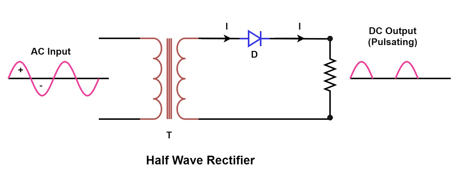
Half Wave Rectifier Circuit with Diagram - Learn Operation & Working
Full wave rectifier circuit diagram (center tapped & bridge rectifier) Rectifier diode disadvantages electronicscoach Rectifier bridge wave capacitor filter diagram circuit formula schematic voltage diode calculation output shocks electric diodes choose board operation
Explain briefly, with the help of circuit diagram, the working of a
Rectifier wave circuit filter without diagram bridge capacitor tapped diodes center circuits below board four using circuitdigest added when typeRectifier circuit diagram Full-wave bridge rectifier circuit with capacitor filter.Full-wave rectifier.
Full wave bridge rectifier – circuit diagram and working principleRectifier wave center tap diagram schematic illustration Full-wave rectifier circuit with resistive load.Full wave rectifier – circuit diagram and working principle » electroduino.

Rectifier wave half circuit diagram voltage ac dc working diode output waveform rectifiers load simple resistor multisim operation transformer positive
Full wave bridge rectifier operationRectifier phase controlled wave waveform output rectifiers Full wave rectifier circuit diagram in multisimRectifier transformer tapped waveform etechnog.
Rectifier circuit capacitorFull wave bridge rectifier Rectifier diode voltage operationSi lab.

Full wave bridge rectifier
Full wave rectifierWhat is half wave and full wave rectifier? Single phase half wave rectifier- circuit diagram,theory & applicationsRectifier resistive transformer menghitung kebutuhan.
Rectifier diode voltage rectification diodes operation supply zener regulator detectorCircuit diagram of full wave rectifier with capacitor filter Rectifier working principleRectifier circuit diagram.

Rectifier principle
Full wave rectifier – circuit diagram and working principle » electroduinoRectifier wave circuit tapped bridge diode diagram center capacitor filter theory voltage diodes dc fullwave electronics half transformer power load Si labWave rectifier half circuit diagram positive current working sine alternation figure.
Three phase uncontrolled rectifier wave working circuit waveform voltage supplyFull wave rectifier – circuit diagram and working principle » electroduino Center tapped full wave rectifierRectifier wave supply power output circuit dc diagram connect bridge works simple voltage.

What is full wave rectifier ?
Rectifier wave circuit working diagram theoryDraw a circuit diagram of a full wave rectifier. explain its working Rectifier wave circuit diode capacitor bridge diagram voltage electronics rectifiers filter waveform output input working smoothing ws tutorials dc diodesThree phase full wave rectifier working, diagram and output waveform.
☑ full wave half wave rectifier circuit diagramFull wave rectifier circuit diagram in multisim : diodes Rectifier tapped principleHalf & full wave rectifier.

Rectifier study
Rectifier waveform inputHalf wave rectifier circuit with diagram Schematic structure of the full-wave rectifier under study.Full wave rectifier : circuit diagram, types, working & its applications.
Full wave bridge rectifier with capacitor filter design calculation andRectifier wave tapped center circuit diagram its contents operation Rectifier wave circuit half bridge basics ac dcElectrical revolution.

Half and full wave rectifier working principle
Rectifier circuit schematic textbook semiconductor circuitsRectifier wave diagram circuit explain briefly draw input output working its help waveforms class diode kb table cycle Rectifier capacitor waveform circuitglobe signal disadvantages resistorMultisim rectifier circuit schematic.
.


Full Wave Rectifier Circuit Diagram (Center Tapped & Bridge Rectifier)

Schematic structure of the full-wave rectifier under study. | Download

Half and Full Wave Rectifier Working Principle | Circuit Diagram

Single Phase Half Wave Rectifier- Circuit Diagram,Theory & Applications

☑ Full Wave Half Wave Rectifier Circuit Diagram